
Rangefinder Design - The sliding element
Viewfinders & Rangefinders > Rangefinder Design - The Sliding Element

One of the most common rangefinder designs is the sliding lens design. As the name implies the design utilises a sliding lens to deflect the light ray coming in, this design has two main advantages. Firstly, it can be placed between the mirror and the beamsplitter, thus utilizing the otherwise wasted space. Secondly, if a plano-concave element is used instead of wedge (essentially approximating a wedge of constantly varying slope) it can replace a plano-concave the widening element of a viewfinder and create a combined rangefinder viewfinder.
Sliding Element Formulas
The sliding element rangefinder makes use of the basic properties of lenses, deviation. At the height h from the center of a lens of focal length f the angle of deviation δ is equal to:
tan δ = h/f
in part 1, the formula:
tan α = b/E
was introduced, where b is the base length and E is the focusing distance. it becomes evident that if we say:
tan δ = tan α
we can use this element to deviate the light by the necessary amount, by simply sliding it, or rotating it along the center of it’s radius, changing the height at which the beam passes through it. Of course we can also optimize this design, offseting it by h/2 to use both sides of the glass element. It’s just important to remember that the mirror also has to be offset by α/4,
why α/4? Well if we’re moving the element over by half of h then the angle δ is also divded by 2 (small angle approximation). α = δ, thus the mirror has to be adjusted to correct for half of this offset, so α/4.
Since these calculations were not available in any previous source, I had to deduce them. I therefore went through some more testing using ray tracing software to prove that the results correlated with what I had come up with.
For the Following graphs, a hypothetical rangefinder with the following specs was used:
b=50
minimum focusing distance = 1.25m
Cylindrical Element focal length = 50mm
Cylindrical Element height = 2mm
The graphs on the right show the angle of the beam exiting the PCX eyepiece element, and how much it diverges from the correct value (0 degrees) depending on the focusing distance, and the distance from the light ray to the principal axis. One graph shows these values when the lens element is displaced linearly, and the other rotationaly around the center of it’s radius. It can be easily seen that the linear values deviate less around the principal axis, and are thus technically more accurate, but making this kind of displacement is not as easy as the rotational one, so most manufacturers don’t use it.
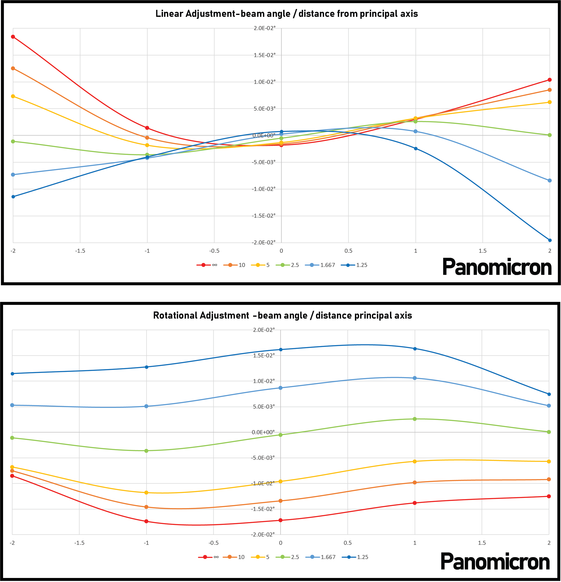

focusing deviation / focusing distance
The rotational adjustment has a lot more error across the board, but is quite consistent, the curvature isn’t as strong as for the linear adjustment. Now, it’s important to remember, this error new goes out of the range of -0.02 to +0.02 degrees. To show how insignificant this really is, here are the most extreme error values for each focusing distance, compared to the DoF of a 50mm f/0.7 lens.
As you can see, it’s well within tolerance for all of the focusing distances tested. At the close focusing range, the line crosses 0 around 2.25m, and looks like it might go out of range in a closer focusing range. This might just be because the focusing element is perfectly centered around 2.5m, and making a rangefinder that focuses closer would correct that value. But even if it that doesn’t correct it, the rangefinder can be adjusted so that the line sits closer to the upper limit when calibrating. As is illustrated in Josef Stüper’s book.
If you think I’ve made a mistake, or something isn’t clear, don’t hesitate to send me an email and I will do my best to address it.